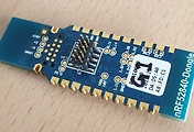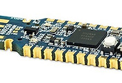
Nordic Semiconductor nRF52840 Development Kit (nRF52840-DK) is a versatile, single-board development tool for Bluetooth® 5 / Bluetooth Low Energy (BLE), 802.15.4 / Thread, ANT/ANT+, and proprietary 2.4GHz applications using the nRF52840 Multi-Protocol SoC (System on Chip). Hardware-compatible with the Arduino Uno Revision 3 standard, the nRF52840-PDK enables designers to use 3rd-party shields that conform to this standard.
The nRF52840-PDK supports the standard Nordic tool-chain software using Keil, IAR, and GCC. Program/debug options are available for Segger J-Link OB and external target boards. The Development Kit gives access to all I/O and interfaces via edge connectors and has four user-programmable LEDs and buttons. Designers can connect an NFC antenna to enable NFC tag functionality.
Features
- 장착칩 : nRF52840
- Prototyping and development platform for the nRF52840 Multi-Protocol SoC
- Arduino Uno shield compatible
- ARM mbed enabled
- All I/O and interfaces available at edge connectors
- Segger J-Link OB Program/Debug supported
- RF SMA connector for direct RF measurements
- Includes flex NFC antenna
- NFC tag-A interface and antenna
- Interfaces directly to Nordic Power Profiler Kit
제품 브리프 (pdf) : https://www.nordicsemi.com/-/media/Software-and-other-downloads/Product-Briefs/nRF52840DKPBv10.pdf
사용자 매뉴얼 : https://kr.mouser.com/pdfdocs/Nordic_nRF52840-DK_UG.pdf
제조사 제품 사이트 : https://www.nordicsemi.com/Software-and-Tools/Development-Kits/nRF52840-DK
보드에 장착된 nRF52840 IC revision 확인방법.
보드의 칩위에 부착된 스티커에 기록된 버전이 1.0.0 이면 IC revision 1, 1.1.0 이면 IC revision 2 .
상세보기 : IC revision 확인정보.
---------------------------------------


Button1,2,3,4.
- 아래사진 우 하 에 보이는것

Button- nRF52840 연결상태.
Button 1 : P0.11 , Button 2 : P0.12, Button 3 : P0.24, Button 4 : P0.25

회로를 보면, 스위치 누른 경우 접지로 연결되는 단순 구조이다. 이런 스위치 구성에서는 MCU 핀 설정시 internal pull up 저항을 설정하지 않으면 스위치 누른 경우는 접지로 연결되어 상태 0이 되지만, 스위치 안누르고 있는 경우엔 floating 상태가 되어 부정 상태가 된다. 따라서, 필수 internal pull up 저항을 설정해야 스위치 안누른 상태에서 핀 상태 high가 되어 식별 가능해진다.
LED1, 2 , 3, 4
- 아래 사진에 4개의 LED 부착된것 볼 수 있다.

LED - nRF52840 연결상태.
LED1 : P0.13, LED2 : P0.14, LED3 : P0.15, LED4: P0.16

위회로 상황에서는 핀 상태가 Low 이면 LED 켜지고, High 이면 꺼진다.

NFC 안테나


보드내장 J-Link USB 연결

PC에 설치되는 드라이버들.

DK 를 J-Link 디버거로 활용하기 : https://igotit.tistory.com/2296
nRF52840 DK 를 J-link 디버거로 활용하기
nRF82840 DK (아래그림의 푸른색 보드) 는 J-Link 가 기본 내장되어있다. 이 보드의 J-Link 를 다른 보드의 nRF52 디버거 용도로 사용가능하다. 방법 아래 사진처럼 nRF52840 DK 보드의 2x5 핀에 케이블 연결하고..
igotit.tistory.com
사용중 먹통 된 경우 조치법.
PCA10056 Not working - Nordic Q&A - Nordic DevZone - Nordic DevZone
devzone.nordicsemi.com
판매처.
개발보드NRF52840-DK 키트 DK Pca10056 블루투스 5.0 개발 보드 노르딕
COUPANG
www.coupang.com
첫등록 : 2018년 5월 31일
최종수정 : 2019년 10월 4일
본 글 단축주소 : https://igotit.tistory.com/1665
'임베디드.일렉트로닉스 > nRF52' 카테고리의 다른 글
| nRF52840 USB동글의 J-link 커넥터 연결하기 (0) | 2019.10.05 |
|---|---|
| nRF52840 USB 동글. PCA10059 (0) | 2019.10.04 |
| nRF52840. KEIL 프로젝트 만들기 . SES 프로젝트 만들기. (0) | 2019.10.04 |
| nRF5 SDK. 개요. 다운로드. (0) | 2019.09.29 |
| 칩. nRF52840. 블루투스 5.0 (0) | 2019.09.29 |


댓글